Biomass
boilers
For
warm water
- BIO
Automated, pellet, wood chips,
- Farmer
Automated, pellet,wood chips,
wood logs, multifuel
- Automat
Self-loading, automated, pellet,
wood chips, multifuel
Steam boilers
- Low pressure steam (0,5bar) automated boilers
for biomass, pellet, wood chips, multifuel
Coal
boilers
- Automated brown coal boilers
For warm water or low pressure steam
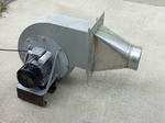
Fuel
feeder systems
|
| Chimney sizes for CARBOROBOT |
|
|
For the CARBOROBOT boilers the necessary
chimney draught is 10-15Pa after 10 minutes when the ventilator
fan is stopped. This is about 8-9m(22-24 foot) aktíve chimney
tube lenght from inlet to the tube end.
Here is some drawings to help to define the chimney
placement
hight
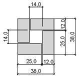
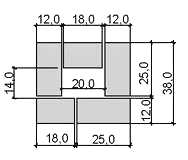
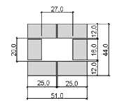
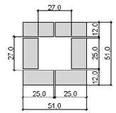
Sizing
1
Sizing
2
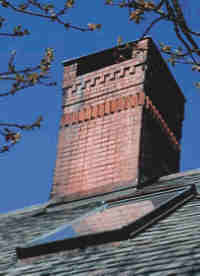
Chimneys can be broken down into two main categories; metal
and masonry. Metal chimneys, also called prefab.
Metal chimney
6 Inch Inside Diameter (28.3 Square Inches)
7 Inch Inside Diameter (38.5 Square Inches)
8 Inch Inside Diameter (50.3 Square Inches)
10 Inch Inside Dia. (78.6 Square Inches)
One thing that we notice from this table is that a 6" flue
is almost 1/2 the size of an 8" flue. The natural tendency
might be to think that a 6" flue is "only" two
inches smaller that an 8" one, but in truth you can see the
difference is much larger.
Masonry Flues
7 1/2 X 7 1/2 (31 Square Inches)
8 1/2 x 8 1/2 (41 Square Inches)
8 1/2 X 13 (70 Square Inches)
13 X 13 (99 Square Inches)
13 X 18 (156 Square Inches)
|
|
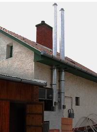
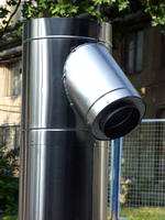
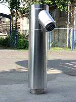
| Masonry and prefab steel tube by
the CARBOROBOT power |
|
|
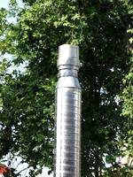
| Prefab stainless steel
chimney |
|
|
|
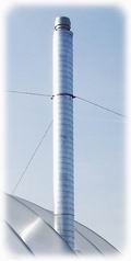
This chimney tubes offered
for the CARBOROBOT boilers inner tube material is stainless steel.
Cover tube is aluminium. Inner tube diameter between 120- 350mm
insulation 30 or 50mm. Possible lenght up to 15m, insulation
500°C or 1200°C
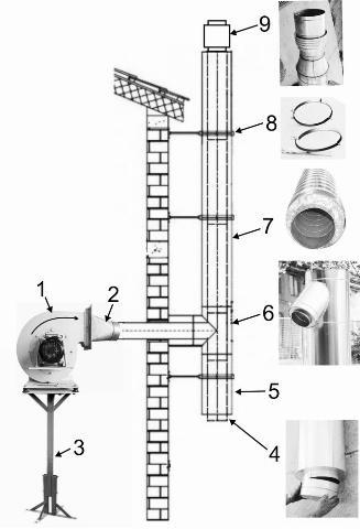
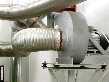
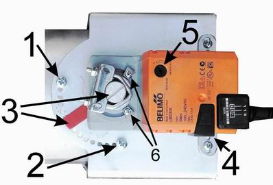
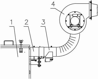
Key elements for mounting
of the flue
1. Fan. This must be installed in line with the flue but also made
sure it is kept dry and remains within the boiler house. If it gets
wet, the cold fan house corrodes quickly.
2. Transition flange(diffuser). This does not come with the boiler
and has to be purchased separately. This allows connection with
boiler to the flue.
3. Fan brackets. By this it is easier to place the fan in the proper
direction. These can be purchased separately if required to hold
the fan. They have rubber mounted 'feet' to reduce any noise produced
by the fan.
4. The flue end cap.
5. Cleaning pipe / water trap. To allow collection of any moisture
collected within the flue and for cleaning of fly ash and other
ash build up.
6. Connection pipe. The fan joins at this point either at 45 or
90 degrees.
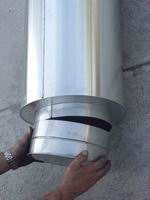
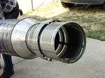
7. Flue pipe. It is assembled by sliding 3-4m parts into each other.
An insulated flue needs to be used. Its insulation is from heat-proof
ceramic wool. The inside tube is acid-proof, the outside cover is
aluminium.
8. Flue fixing clamps
9. Flue end cap should be fitted to stop the effect of high winds
and heavy rain and to block the return-flow. The flue should be
above the roof ridge height to allow natural draw so exhaust gases
can get away easier.
|
|
| Accessories |
|
 Felxibile
stainless steel double wall tube Felxibile
stainless steel double wall tube
|
Fan with diffusor shape
|
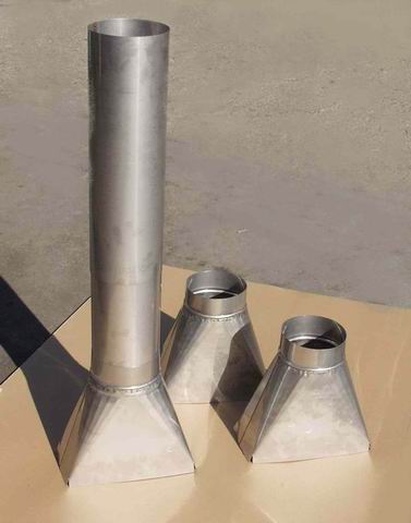
Diffusors and rigid tube
for the fan
|
|
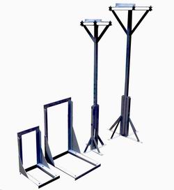
Console types
|
 Noise
reducing mounting assembly for any type (mostly recommended) Noise
reducing mounting assembly for any type (mostly recommended)
|
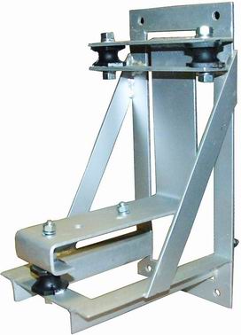
Wall console with rubber
noise amortisators
|
|
| Automatic
flue gas damper |
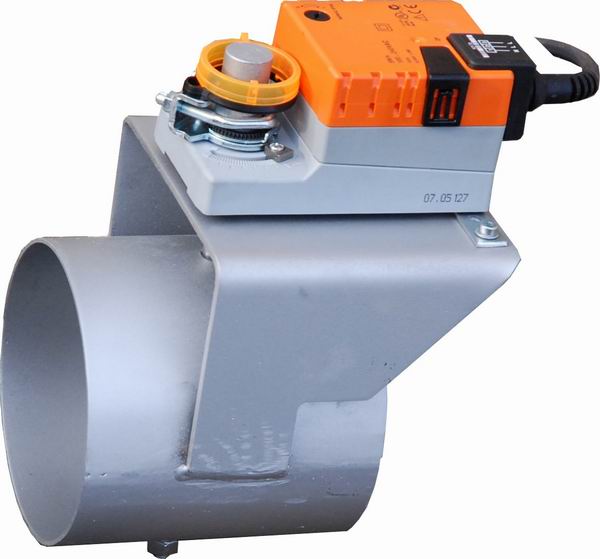 |
 |
1 Boiler
2 Flue outlet
3 Damper
4 Fan.
|
Automatic flue gas damper It is sometimes
necessary to adjust the draft of the flue. Too strong a draft
for some fuels (e.g. wood pellets) can override the control system
of the boiler, so that when the fire should go down, it continues
to burn at a lower rate instead. Furthermore, the damper prevents
the boiler from cooling down too quickly by closing the flap to
reduce the amount of warm air escaping through the chimney. This
improves the efficiency of the boiler.
The opening and closing angles can be adjusted with the 1st and
2nd stop screws , the closing angle shows the 3. nomination.
Attention! A closed damper significantly reduces drafts, so it
is possible that stopping the boiler smoke coming out of vents.
If this happens, then the dampers closed 2. fixing bolt set the
less closed position, to be remainder draft larger, and it can
suck the smoke from the boiler.
The colder winter weather in the chimney terminal draft is larger,
but in warm weather reduced and may require re-adjustment of the
damper. This option is the operator's responsibility.
The buffers marked 6. always set of specified end position so
as not to interfere with the setting screws 1. and 2. With the
5. Reversing buttons may be to adjust when the fan is turned on,
open, or close the damper. (of course, to open in this case)
The mechanical uncoupling hand button 4. can be disconnect the
gears, so possible freely adjust the damper. If you let go the
button, the engine will automatically to the end position turn
the flap again.
The damper must be installed on the boiler
flue outlet. In all cases, the engine bottom, or side to place.
Never mount the engine upper position, above the flue tube, because
of the rising hot air melts the engine.
The damper has two positions: closed when the fan is off - and
open when the fan is on (i.e. the boiler is firing)
In operation the damper is automatically controlled together with
the fan. It takes 30 seconds for the flap to change position.
The drive motor running with 230V.
Damper connecting:
- White wire: 230V at the same time switch on / off Line together
with the fan
- Brown wire: Continuous 230V Line
- Blue wire: Neutral, continuous
110-130-150-180-200-250 mm diameters
Heat load. max.350 °C.
|
|

